Earthing (grounding) system according to IEC, BS-EN and IEEE standards
페이지 정보
작성자 관리자 댓글 0건 조회 504회 작성일 22-10-17 09:33본문
Resistivity of soil
Resistivity measurements for good earthing (grounding) system according to IEEE Std 80-2000
(…) A number of measuring techniques are described in detail in IEEE Std 81-1983. The Wenner four-pin method, as shown in Figure below, is the most commonly used technique. In brief, four probes are driven into the earth along a straight line, at equal distances a apart, driven to a depth b. The voltage between the two inner (potential) electrodes is then measured and divided by the current between the two outer (current) electrodes to give a value of resistance R.
Wenner four-pin method
then for b « a:![]()
where
ρa– is the apparent resistivity of the soil in Ωm
R – is the measured resistance (R=U/l) in Ω
a – is the distance between adjacent electrodes in m
b – is the depth of the electrodes in m
Resistivity for types of soil according to IEC 60364-5-54:2011
| Nature of ground | Resistivity [Ωm] |
| Marshy ground Alluvium Humus Damp peat | From some units to 30 20 to 100 10 to 150 5 to 100 |
| Malleable clay Marl and compact clay Jurassic marl | 50 100 to 200 30 to 40 |
| Clayey sand Siliceous sand Bare stony soil Stony soil covered with lawn | 50 to 500 200 to 3 000 1 500 to 3 000 300 to 500 |
| Soft limestone Compact limestone Cracked limestone Schist Mica-schist | 100 to 300 1 000 to 5 000 500 to 1 000 50 to 300 800 |
| Granite and sandstone according to weathering Granite and very altered sandstone | 1 500 to 10 000 100 to 600 |
Step 3
Good conductors and rods for earthing (grounding) system according to IEC/BS EN 62561-2:2012
Material, configuration and cross sectional area of earth electrodes
| Material | Configuration | Cross sectional area a) | Recommended dimensions | |
| Copper coated steel c) | Solid round | ≥ 150 h) | 14 mm diameter, if 250 µm minimum radial copper coating, with 99.9% copper content | |
| Solid round | ≥ 50 | 8 mm diameter, if 250 µm minimum radial copper coating, with 99.9% copper content | ||
| Solid round | ≥ 78 | 10 mm diameter, if 70 µm minimum radial copper coating, with 99.9% copper content | ||
| Solid tape | ≥ 90 | 3 mm thickness, if 70 µm minimum radial copper coating, with 99.9% copper content | ||
a) Manufacturing tolerance – 3%
c) The copper shall be intrinsically bonded to the steel. The coating can be measured using an electronic coating measuring thickness instrument
h) In some countries, the cross sectional area may be reduced to 125 mm²
Step 4
Good cross section of earthing conductors according to IEEE Std 80-2000
11.2.2 Copper-clad steel
(…) Copper-clad steel is usually used for underground rods and occasionally for grounding grids, especially where theft is a problem. Use of copper, or to a lesser degree copper-clad steel, therefore assures that the integrity of an underground network will be maintained for years, so long as the conductors are of an adequate size and not damaged and the soil conditions are not corrosive to the material used.
Calculation of the cross section of earthing conductors based on IEEE standards 80-2000
A – earthing conductor cross section in mm²
I – rms current in kA
TCAP – thermal capacity per unit volume in J/(cm³ °C)
tc – duration of current in s
αr – thermal coefficient of resistivity in 1/°C
ρr – resistivity of the ground conductor in mΩ-cm
Ko – 1/α o or (1/α r) – Tr in °C
Tm – maximum allowable temperature in °C
Ta – ambient temperature in °C
Samples cross section for copper clad conductors with different rms current in kA (I) and duration of current in s (tc)
A) Φ 8 mm – 50 mm²
B) Φ 10 mm – 78 mm²
C) 20 x 3 mm – 60 mm²
D) 25 x 3 mm – 75 mm²
E) 30 x 3 mm – 90 mm²
F) 30.5 x 3 mm – 105 mm²
G) 30 x 4 mm – 120 mm²
H) 40 x 4 mm – 160 mm²
I) 40 x 5 mm – 200 mm²
Step 5
In the points from 4A to 4D there are the guidelines to design earthing (grounding) systems to the particular building facilities and structures according to the standards for these facilities.
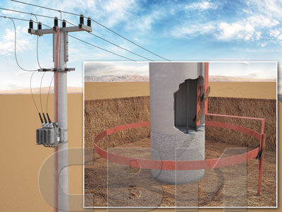
GROUNDING SYSTEM OF TRANSMISSION LINE TOWER (HV AND MV)
BS EN 50522:2010

Resistance of the tower ground ring:
![]()
D = L/π– iameter of the ring in m
L – length of the ring tape in m
d – half the width of the tape in m
ρE – soil resistivity in Ωm
Resistance of the grounding rod with depth h:![]()
L – length of the grounding rod in m
d – diameter of the grounding rod in m
ρE – soil resistivity in Ωm
Resistance of the grounding system:![]()
As the tapes and vertical rods of the external rods system are connected with the steel immersed in the stop footing concrete of the antenna tower, they have to made of precious metals, such as copper-bonded steel, stainless steel or solid copper. Copper-bonded steel materials were applied in the presented installation. This allowed to decrease the grounding (earthing) costs by 45% comparing to the stainless steel or solid copper.
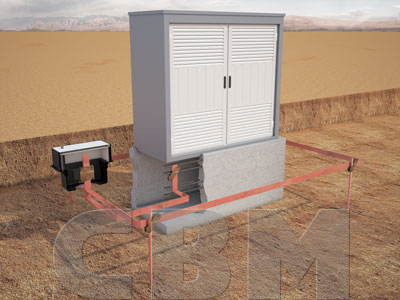
POWER STATION (HV and MV)
IEEE Std 80-2000